Building your own solar panel science project from scratch offers students a hands-on pathway to understanding photovoltaic principles, energy conversion, and renewable technology—the same foundational concepts that power industry-standard solar installations. When you learn how to build a solar panel science project, you're not just assembling a demonstration model; you're developing schema around electrical circuits, voltage-current relationships, and the photoelectric effect that NGSS standards emphasize in middle and high school physical science. This project suits students ages 10 and up with basic circuit experience, requires approximately 3-4 hours of focused work time, and produces a functional solar cell capable of powering small DC motors or LED arrays—tangible proof that renewable energy concepts translate directly into real-world applications.
What You'll Need
Materials for the Solar Cell:

- Six copper flashing sheets (6" x 6" each, 99.9% pure copper—available at hardware stores)
- Table salt (non-iodized, approximately 2 tablespoons per panel)
- Empty clear plastic bottles (2-liter soda bottles work well)
- Stainless steel alligator clip leads (minimum 18 AWG wire gauge)
- Small DC motor (1.5-3V) or LED diode for output demonstration
- Multimeter with voltage and current measurement capability
Tools:
- Electric stove or hot plate (adult supervision required)
- Sandpaper (220-grit for surface preparation)
- Scissors or utility knife
- Measuring cup and mixing container
- Safety goggles and heat-resistant gloves
Prerequisites:
- Basic understanding of electrical circuits (voltage, current, resistance)
- Adult supervision for heating elements and sharp tool use
- Clean, ventilated workspace with access to water
- Familiarity with multimeter operation (or willingness to learn—this project scaffolds that skill beautifully)
Optional Enhancement Materials:
- Solar panel efficiency measurement tools (see How to Measure Solar Panel Efficiency in Science Projects for detailed guidance)
- Data logging software compatible with your multimeter
- 3D-printed mounting brackets for panel positioning (if you have access to FDM printing equipment)
Understanding the Science Behind Your Solar Panel
Before we dive into construction, let's establish the conceptual framework you're building. This isn't a commercial silicon photovoltaic cell—those require industrial fabrication—but rather a cuprous oxide solar cell, which operates on the same photoelectric principles that Einstein won his Nobel Prize explaining. When light strikes certain materials, it excites electrons into higher energy states, creating a voltage difference you can harness.
The copper oxide layer you'll create acts as a semiconductor. When sunlight hits it, photons transfer energy to electrons in the copper oxide crystal structure, freeing them to move through your circuit. This is precisely how professional solar installations generate electricity, just with more refined materials and engineering optimization. I've watched hundreds of sixth-graders struggle with the misconception that solar panels "store" energy—they don't. They convert light energy directly into electrical current in real time, which is why your panel's output will fluctuate with light intensity.
Your homemade panel will generate modest voltage (typically 0.1-0.3V per cell in full sunlight) but the conceptual learning is identical to commercial systems. This project builds understanding of the Fermi level, band gap energy, and semiconductor physics—terminology students encounter again in high school chemistry and college-level material science courses. For context on how solar projects compare to other renewable energy builds, explore Solar vs Wind Energy Projects: Which STEM Kit Is Better for Learning?.
If you're integrating this into a broader renewable energy curriculum, check What Is Renewable Energy for Kids: A STEM Learning Guide for age-appropriate conceptual scaffolding. The understanding you build here translates directly into more advanced projects like the renewable energy science fair presentation many of my students tackle in eighth grade.
Step 1: Prepare Your Copper Sheets
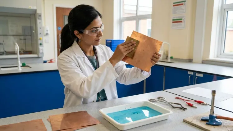
Cut each copper flashing sheet into clean 6" x 6" squares using sharp scissors or a utility knife. Wear safety goggles during cutting—copper edges can be surprisingly sharp, and I've seen too many students get distracted and nick themselves. Use the sandpaper to thoroughly clean one side of each copper square, removing any oxidation, oils, or protective coatings. You'll know you're done when the surface shows bright, uniform metallic luster with no dark spots or discoloration.
This surface preparation step is critical for electron flow. Any contaminants create resistance barriers that reduce your cell's efficiency. In industrial solar manufacturing, this same principle applies—wafer purity directly correlates with panel output. The difference is that silicon wafer fabrication happens in clean-room environments with parts-per-million contamination standards, while you're working at a kitchen table. That's perfectly fine for learning the underlying physics.
Rinse each cleaned copper sheet under running water, then dry completely with a lint-free cloth. Water spots create uneven heating in the next step, which can crack your copper oxide layer before it fully forms. Handle the cleaned surfaces by the edges only—skin oils reduce semiconductor performance.
Step 2: Heat-Treat the Copper to Form Cuprous Oxide
Place one copper sheet directly on your electric stove burner or hot plate set to maximum heat. Adult supervision is mandatory here—we're working with temperatures around 500°F. Watch as the copper gradually changes color, transitioning from orange to brown to black as copper oxide forms on the surface. This process typically takes 20-30 minutes depending on your heat source.
The color changes you're observing represent actual chemical transformation. The black coating is cupric oxide (CuO), but beneath it, you're forming a layer of cuprous oxide (Cu₂O)—the semiconductor material that actually generates your photovoltaic effect. Different copper oxide crystal structures have different electronic properties, which is why oxidation depth and uniformity matter for performance.
Continue heating until the copper sheet is completely black with no orange patches remaining. Then—and this is counterintuitive for many students—turn off the heat and let the copper cool naturally on the burner for at least 30 minutes. Do not quench it in water or move it to a cooling rack. Rapid temperature changes crack the oxide layer, destroying its semiconductor properties. I've seen entire class sets of panels ruined by impatient students who tried to speed up cooling.
As the copper cools below approximately 200°F, something remarkable happens: the black cupric oxide layer begins to flake off naturally, revealing the reddish-brown cuprous oxide semiconductor underneath. You can gently encourage this process by flexing the cooled sheet slightly, but don't scrub or scratch the surface. You want to preserve that Cu₂O layer intact.
Step 3: Construct Your Solar Cell Container

Cut the top section off a clear 2-liter plastic bottle, creating a shallow container approximately 4-5 inches tall. The container needs to be transparent to admit sunlight and deep enough to hold your copper sheets upright without touching. Rinse the container thoroughly to remove any residue—sugar from soda creates electrical resistance paths through your electrolyte solution.
Place one heat-treated copper sheet (with the red-brown cuprous oxide surface exposed) along one inside wall of your container. Position a second, untreated copper sheet (shiny side facing inward) along the opposite wall. The two sheets must not touch each other—if they make contact, you'll create a short circuit that bypasses your solar cell entirely. Maintain at least 1 inch of separation between sheets.
This arrangement creates what's called a photoelectrochemical cell. The cuprous oxide sheet functions as your photoanode (where light excites electrons), the untreated copper acts as your cathode (where electrons return), and the salt solution you'll add next serves as the electrolyte that allows current to flow between them. Commercial silicon solar panels use different materials but the same fundamental charge-separation architecture.
Bend small tabs at the top of each copper sheet to hook over the container rim, holding them in position. These tabs also serve as your electrical connection points. The geometry matters here—you want maximum surface area exposed to both sunlight and electrolyte solution for optimal current generation.
Step 4: Prepare and Add Electrolyte Solution
Mix 2 tablespoons of non-iodized table salt into 2 cups of warm water, stirring until completely dissolved. The salt concentration creates your electrolyte—a solution that conducts electricity by allowing charged particles (sodium and chloride ions) to move freely between your electrodes. In commercial solar panels, electron flow happens through solid-state junctions instead, but the principle of charge carrier mobility remains identical.
Pour the salt solution into your container until both copper sheets are submerged about 80% of their height. Leave the top tabs exposed—those are your electrical connections, and submerging them would allow current to leak into the solution rather than flowing through your external circuit. The solution should appear completely clear. If it's cloudy, you've got contamination that will reduce efficiency.
The electrolyte serves a second crucial function: it prevents the cuprous oxide layer from continuing to oxidize in air. Semiconductor properties are fragile—the specific Cu₂O crystal structure you've created would gradually degrade if exposed to atmospheric oxygen. The saline environment stabilizes your photovoltaic material, extending your panel's functional lifetime from hours to several weeks if properly maintained.
You've now built a complete solar cell. The cuprous oxide absorbs photons, excited electrons travel through your external circuit to do useful work, and they return via the electrolyte to complete the circuit. This is precisely the electron pathway that powers the solar energy kits in commercial science projects, just with more refined engineering.
Step 5: Wire Your Circuit and Test Output
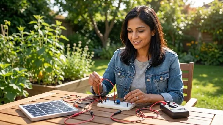
Attach one alligator clip lead to the tab of your cuprous oxide copper sheet (the red-brown one)—this is your negative terminal. Attach a second lead to the untreated copper sheet tab—your positive terminal. Students often assume the oxidized sheet would be positive since we "added" material, but electron flow physics works opposite to their intuition. The oxidized sheet releases electrons when illuminated, making it the negative electrode.
Connect your multimeter to these leads, set to DC voltage measurement mode (typically the "V⎓" setting). In dim indoor lighting, you should read approximately 0.1-0.2 volts. Now carry your panel assembly outside into direct sunlight. Watch the voltage reading climb—you should see 0.25-0.35V in full midday sun. That voltage proves photons are exciting electrons in your semiconductor material.
Switch your multimeter to current measurement mode (often requires moving the red probe to a different jack—consult your meter's manual). You'll measure current in microamps (µA) or milliamps (mA), likely in the range of 10-50 µA for a single cell. That's modest current, but it's real electrical power generated entirely from sunlight. If you connect multiple cells in series (positive of one to negative of the next), voltages add together, just like connecting batteries. Six cells in series should generate enough voltage to visibly dim an LED or make a small motor twitch.
This testing phase validates your understanding of circuit principles. You're measuring voltage (electrical potential difference) and current (charge flow rate)—the same parameters electrical engineers monitor in utility-scale solar farms. The only difference is magnitude, not physics.
Step 6: Optimize and Document Performance
Once you've confirmed your panel generates voltage and current, it's time to conduct systematic performance testing. Move your panel to different lighting conditions and record voltage/current measurements for each: direct sunlight, cloudy sky, shade, indoor near a window, and under an incandescent bulb. Create a data table tracking light conditions, voltage, current, and calculated power output (P = V × I).
This documentation process mirrors industry-standard photovoltaic characterization. Professional solar engineers create current-voltage curves (I-V curves) to evaluate panel performance under varied conditions. You're building those same analytical skills at a developmentally appropriate level. For students continuing into high school physics, this data set provides excellent material for graphing, curve fitting, and discussing efficiency variables.
Experiment with panel angle relative to your light source. You should observe maximum output when the panel surface is perpendicular to incoming light—this is why commercial solar installations use sun-tracking mechanisms. Measure output at 0°, 30°, 45°, 60°, and 90° angles. Your data will reveal the cosine relationship between angle and effective light intensity, connecting your solar project to trigonometry concepts.
If you have access to multiple panels, test series versus parallel configurations. Series connections (positive to negative) add voltages while keeping current constant. Parallel connections (all positives together, all negatives together) add currents while keeping voltage constant. Understanding these relationships prepares students for the renewable energy science experiments they'll encounter in advanced coursework.
Step 7: Connect a Load and Demonstrate Real Work
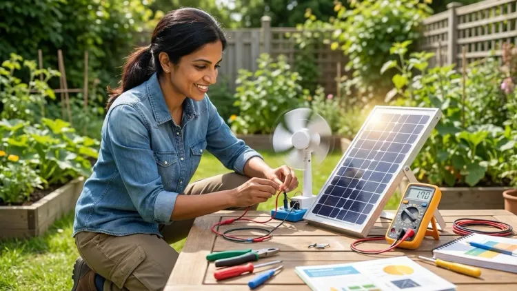
The ultimate validation of your solar panel comes from powering an actual device. Connect your panel (or a series array of multiple panels) to a small DC motor in the 1.5-3V range—the type found in toy cars or used in basic robotics projects. Place your assembly in direct sunlight and watch carefully. You should see the motor shaft begin to rotate, slowly at first, then more consistently as the sun reaches optimal angle.
That spinning motor shaft represents mechanical work performed using only photon energy. The sunlight hitting your cuprous oxide semiconductor has excited electrons into conducting states, those electrons flow through the motor windings creating magnetic fields, and those fields generate torque that rotates the shaft. You've converted light to electricity to mechanical motion—the same energy transformation chain used in solar-powered vehicles, satellites, and remote sensors.
If your motor doesn't run immediately, troubleshoot systematically. Check all electrical connections for solid contact. Verify the motor's voltage rating—if it requires 3V and you're supplying 0.3V, you won't generate enough torque to overcome friction. Try connecting six cells in series for cumulative voltage. Ensure you're testing in genuine direct sunlight, not through a window—glass absorbs significant UV radiation that contributes to photoelectric effect.
For students interested in quantifying this energy conversion, calculate your motor's power consumption (P = V × I) and compare it to the incident light energy hitting your panel surface. The ratio reveals your overall system efficiency—typically well below 1% for cuprous oxide cells compared to 15-20% for commercial silicon panels. That efficiency gap explains why industry uses refined materials, but the fundamental physics remains identical.
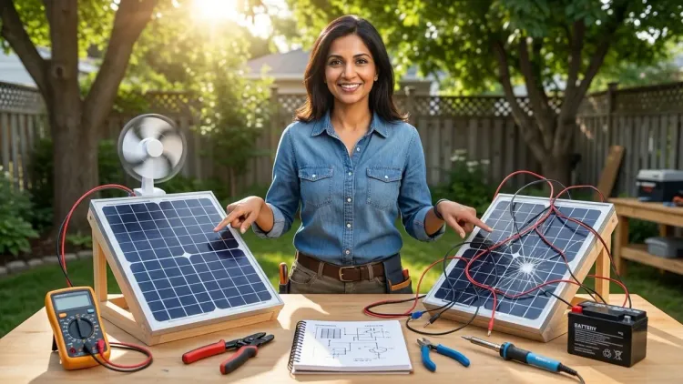
Step 8: Scale Your Project and Explore Variables
With a working prototype, you can now investigate variables that affect solar cell performance—this is where the project transforms from construction exercise into genuine experimental science. Design controlled experiments testing one variable at a time while holding others constant. Does salt concentration affect output? Try solutions with 1, 2, and 4 tablespoons of salt per 2 cups of water, measuring voltage for each.
Does copper sheet size matter? Build cells with 3"×3", 6"×6", and 9"×9" copper squares, keeping solution concentration and electrode spacing identical. Larger surface area should increase current (more photons hit more semiconductor material) while voltage remains relatively constant—this test builds understanding of how panel geometry relates to electrical output.
How does aging affect performance? Measure your panel's output daily over two weeks. You should observe gradual decline as the cuprous oxide layer continues oxidizing or as the copper dissolves slightly into the electrolyte. This degradation mirrors real-world solar panel performance curves—commercial panels lose approximately 0.5-1% efficiency per year, requiring replacement after 25-30 years.
Students preparing for science fair presentations should document these experiments with photographs, data tables, and graphs. The renewable energy science fair projects checklist provides scaffolding for translating your hands-on work into compelling presentation format. Your homemade solar panel becomes the foundation for demonstrating genuine experimental design and data analysis skills—capabilities that matter far more than the specific project topic.
Pro Tips & Common Mistakes
Temperature control during oxidation makes or breaks your panel. Too little heat produces incomplete oxidation that won't function as a semiconductor. Too much heat oxidizes so deeply that you get thick, flaky layers with poor adhesion. The sweet spot is full black coloration with oxide layers that naturally curl away during cooling. If your black layer doesn't flake off when cool, you likely didn't heat long enough—the underlying cuprous oxide never properly formed.
Electrode spacing affects internal resistance. Students often cram copper sheets right next to each other to "improve" electron flow, but ions must travel through the electrolyte between electrodes. Position sheets 1-2 inches apart for optimal balance between light exposure and electrolyte conductivity. I've watched countless students troubleshoot low output that was entirely attributable to sheets touching each other and creating short circuits.
Solution maintenance matters for longevity. Your panel will gradually lose performance as the salt concentration changes through evaporation. Top off with distilled water weekly to maintain consistent electrolyte strength. If performance drops suddenly, the copper sheets may have shifted position—check that they're still separated and fully submerged.
Realistic expectations prevent frustration. Homemade cuprous oxide solar cells generate milliwatts of power—enough to demonstrate principles but not enough to charge your phone. Students sometimes feel disappointed by the modest output until they understand they've built a learning tool, not a practical power source. Frame the project correctly from the start: we're replicating photovoltaic physics at a molecular level, which is conceptually identical to commercial panels regardless of power output magnitude.
For students ready to transition from this hands-on build to examining commercial renewable energy options, the best solar energy kits for science projects offer pre-engineered silicon cells with significantly higher efficiency, allowing focus on circuit design and load calculations rather than cell fabrication.
Frequently Asked Questions
How long does it take to build a working solar panel science project from scratch?
Building a functional cuprous oxide solar panel from scratch typically requires 3-4 hours of active work time spread across two sessions—one for copper oxidation (allowing for cooling time) and a second for assembly and testing. The heat treatment step alone takes 30 minutes of heating plus 30 minutes of controlled cooling, so plan your timeline accordingly to avoid rushing this critical phase where patience directly impacts semiconductor quality.
Can I use aluminum foil or other metals instead of copper sheets?
No, copper is specifically chosen because it forms cuprous oxide (Cu₂O), which functions as a semiconductor with appropriate band gap energy for visible light photons. Aluminum forms aluminum oxide, which is an insulator rather than a semiconductor, and won't generate photovoltaic effect. Other metals like zinc or tin form oxides with incorrect electronic properties for solar energy conversion, so stick with 99.9% pure copper flashing for reliable results that demonstrate proper photoelectric principles.
Why does my solar panel only produce a tiny amount of electricity?
Cuprous oxide solar cells have inherently low efficiency (typically under 1%) compared to commercial silicon panels (15-20% efficiency) because the Cu₂O band gap and crystal structure aren't optimized for photovoltaic applications the way refined silicon is. Your panel demonstrates the correct physics of light-to-electricity conversion but uses materials that are easy to work with at home rather than industrially optimized semiconductors, so modest output is completely expected and doesn't indicate construction errors.
How does this homemade solar panel project connect to real-world renewable energy technology?
Your cuprous oxide cell operates on identical photoelectric principles that power utility-scale solar farms—photons excite electrons in semiconductor materials, creating voltage differences that drive current through external circuits. The Department of Energy's solar energy research division uses the same fundamental physics you're demonstrating, just with refined materials (monocrystalline silicon, gallium arsenide, or perovskite compounds) engineered for maximum efficiency. Students who understand your homemade panel's operation can directly translate that knowledge to analyzing commercial renewable energy systems.
Summary
Learning how to build a solar panel science project from scratch using copper oxidation teaches the photoelectric effect, semiconductor physics, and energy conversion principles that underlie the entire solar power industry. You've created cuprous oxide through controlled heat treatment, assembled a photoelectrochemical cell with proper electrode geometry, and measured real electrical output generated entirely from sunlight—the same electron excitation process that Ernest Rutherford and Albert Einstein pioneered understanding over a century ago. The modest power output you achieve doesn't diminish the conceptual learning; you've built schema around how photons interact with crystalline structures to free charge carriers, knowledge that transfers directly to understanding commercial silicon solar technology, band gap engineering, and the semiconductor physics that power modern renewable energy infrastructure. This foundation prepares students for advanced coursework in electrochemistry, material science, and the engineering challenges of scaling laboratory demonstrations into grid-level power generation.