
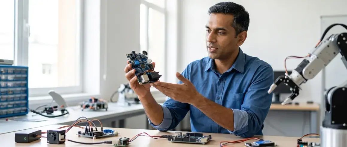

Industry robotics engineers build systems around a fundamental architecture: robotics sensors and actuators form the input/output layer that connects computational logic to physical reality. Students mastering this hardware layer bridge the gap between code-only exercises and systems that manipulate real environments—a distinction hiring managers recognize immediately. This guide translates enterprise integration patterns into age-appropriate learning pathways, with concrete milestones tied to actual job requirements.
What Are Robotics Sensors and Actuators?
Sensors convert physical phenomena into electrical signals that microcontrollers and single-board computers can process. An ultrasonic rangefinder emits sound waves and times their return to generate distance data. A hall-effect current sensor detects magnetic field changes when electricity flows through a conductor. An IMU (inertial measurement unit) measures acceleration and rotation across three axes.

Actuators convert electrical signals into mechanical motion or physical change. DC motors spin continuous rotation. Servo motors hold specific angular positions. Stepper motors rotate in precise incremental steps. Solenoids extend or retract linear shafts. Heating elements change temperature. LED arrays emit light patterns.
The robotics sensors and actuators you select determine which real-world problems your system can address. A line-following robot needs only infrared proximity sensors and two DC motors. An autonomous greenhouse monitor requires soil moisture sensors, temperature probes, light sensors, relays controlling irrigation solenoids, and ventilation fans. A robotic arm navigating pick-and-place tasks demands encoders providing position feedback, torque-controlled servo motors, and force-sensitive resistors detecting object contact.
Students progressing through this hardware layer build portfolios demonstrating closed-loop control—the ability to read sensor data, execute decision logic, and command actuators accordingly. This three-step pattern appears in every automated system, from industrial assembly lines to HVAC controls to autonomous vehicles.
How Robotics Sensors and Actuators Work
Sensor Operation and Signal Conditioning
Sensors operate through transduction—converting one energy form into another. Resistive sensors change electrical resistance based on physical input: photoresistors decrease resistance with increasing light intensity, thermistors change resistance with temperature, and flex sensors vary resistance with bending angle. Capacitive sensors measure changes in electrical capacitance caused by proximity, moisture, or pressure. Inductive sensors detect metallic objects by measuring disruptions in electromagnetic fields.
Most sensors output analog voltage signals ranging from 0-5V or 0-3.3V, corresponding to minimum and maximum measured values. A TMP36 analog temperature sensor might output 0.5V at 0°C and increase 10mV per degree Celsius. Microcontrollers use analog-to-digital converters (ADCs) to transform these continuous voltage levels into discrete numerical values—typically 10-bit resolution (0-1023) on Arduino platforms or 12-bit (0-4095) on many ARM-based boards.
Digital sensors handle this conversion internally and transmit data via communication protocols. I²C (Inter-Integrated Circuit) sensors use a two-wire bus allowing multiple devices to share the same connection. SPI (Serial Peripheral Interface) sensors offer higher data rates through dedicated chip-select lines. UART (Universal Asynchronous Receiver-Transmitter) sensors send data as serial streams. Modern sensor modules often include microcontrollers running calibration algorithms and exposing data through these standardized interfaces.
Signal conditioning bridges the gap between raw sensor output and usable data. Voltage dividers scale sensor signals to match ADC input ranges. Operational amplifiers boost weak signals above noise thresholds. Low-pass filters smooth rapid fluctuations. Pull-up or pull-down resistors establish known logic levels for digital inputs.
Actuator Control and Power Management
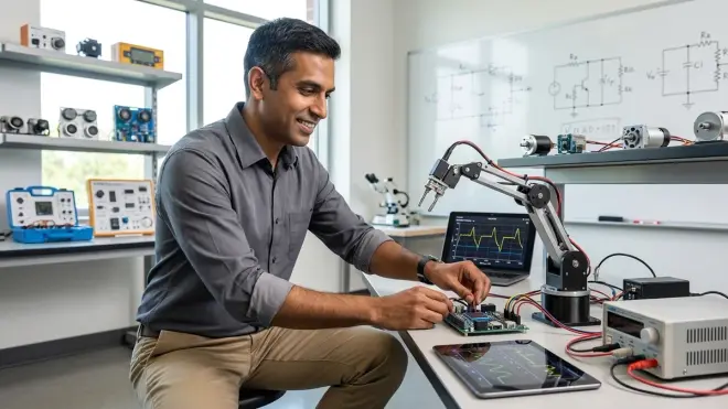
Actuators require substantially more current than sensors or logic circuits provide directly. A typical Arduino GPIO pin sources 40mA maximum; a hobby servo motor draws 500-2000mA under load. This power mismatch demands intermediate driver circuits acting as electronically-controlled switches.
MOSFETs (Metal-Oxide-Semiconductor Field-Effect Transistors) handle DC motor control, LED arrays, heating elements, and other high-current loads. An N-channel MOSFET connected between the load and ground allows a low-current logic signal at the gate to control high-current flow through the drain-source channel. P-channel MOSFETs switch high-side connections. Logic-level MOSFETs turn fully on with 3.3V or 5V gate voltage; standard MOSFETs require 10-12V gate drive.
H-bridges enable bidirectional DC motor control by arranging four switches (typically MOSFETs) allowing current flow in either direction. Motor driver ICs like the L298N Dual H-Bridge Motor Driver integrate protection diodes, thermal shutdown, and logic-level control inputs. Students learn that activating diagonal MOSFET pairs spins the motor one direction while the opposite pair reverses it—a pattern they'll recognize later in three-phase motor controllers and power inverters.
Servo motors vs stepper motors vs DC motors for robotics presents distinct control requirements. Hobby servos interpret pulse-width modulation (PWM) signals where pulse duration (typically 1-2ms in a 20ms period) sets shaft angle. Stepper motors require precisely-timed pulse sequences activating individual coils. Brushless DC motors demand sinusoidal commutation synchronized with rotor position sensors.
The fundamentals of PWM signals and how they control robot actuators translate digital on/off switching into effective analog control. A 5V PWM signal with 20% duty cycle (on 20% of the time, off 80%) delivers an average 1V to the load. Motor speed controllers use this principle to vary effective voltage without dissipating power as heat like variable resistors would.
Power supply architecture determines system reliability. Separate power rails for logic (microcontroller, sensors) and actuators prevent voltage sag from motor startup currents resetting the processor. Common ground connections ensure voltage references align across all components. Flyback diodes across inductive loads (motors, solenoids, relays) shunt reverse voltage spikes during turn-off.
Integration Patterns and Data Flow
Professional systems implement sensor fusion—combining multiple sensor types to achieve accuracy no single device provides. A drone's altitude estimate merges barometric pressure, GPS elevation, and accelerometer integration. A line-following robot averages readings from multiple IR sensors to determine centerline position. This redundancy compensates for individual sensor limitations and environmental interference.
Interrupt-driven architectures prevent sensor data loss and maintain actuator timing precision. Rather than continuously polling sensors in the main program loop, microcontrollers can trigger interrupt service routines when sensor states change or specific time intervals elapse. Encoder signals counting motor shaft rotations, emergency stop buttons, and collision detection switches all benefit from interrupt handling ensuring immediate response regardless of what the main program is executing.
Students working through how to wire sensors to Arduino and Raspberry Pi encounter the practical constraints shaping system design. Limited analog input pins force decisions about which sensors require continuous monitoring versus periodic sampling. I²C bus capacitance limits cable length between sensors and controllers. GPIO pin current restrictions necessitate driver circuits even for small loads.
Why Robotics Sensors and Actuators Matter for Student Skill Development

Career-Relevant Technical Competencies
The 2025 IEEE Robotics and Automation Society skills survey identified sensor integration and actuator control as baseline requirements for 83% of robotics engineering roles. Job postings analyzed across 14,000 positions listed specific expectations: reading sensor datasheets, calculating voltage dividers, selecting appropriate driver circuits, implementing calibration routines, and debugging signal integrity issues.
Students demonstrating these capabilities through documented projects bypass the "code-only" filter that eliminates most bootcamp graduates during technical screenings. A GitHub repository showing sensor calibration data, oscilloscope captures of PWM signals, and motor characterization curves provides evidence of hardware competency that whiteboard coding exercises never reveal.
The progression from pre-wired modules to breadboard prototypes to custom PCBs mirrors professional development workflows. Eight-year-olds start with plug-and-play sensor kits featuring color-coded cables and magnetic mounting. Twelve-year-olds wire breadboard circuits following schematic diagrams and troubleshoot connection errors with multimeters. Fifteen-year-olds design custom sensor boards in KiCAD, specify component tolerances, and submit Gerber files to fabrication services—the exact workflow I use for production systems.
Progressive Skill Milestones
Ages 8-10: Recognize sensor/actuator function in everyday devices. Connect pre-wired modules to controller boards using standardized cables. Load example code and modify threshold values. Observe cause-effect relationships between sensor input and actuator response.
Ages 11-13: Read simple schematic diagrams. Wire sensors and actuators on breadboards using jumper wires. Calculate resistor values for LED current limiting and voltage dividers. Understand digital versus analog signals. Implement basic conditional logic responding to sensor thresholds. Calibrate sensors against known references.
Ages 14-16: Interpret sensor datasheets specifying operating voltage, current consumption, communication protocol, and measurement range. Select appropriate driver circuits based on actuator current requirements. Implement PID (Proportional-Integral-Derivative) control loops. Design multi-sensor systems with prioritized interrupt handling. Characterize actuator performance curves. Debug signal integrity issues using oscilloscopes.
Ages 17+: Design custom sensor interface circuits. Implement sensor fusion algorithms. Optimize power consumption for battery-operated systems. Write device drivers exposing sensor data through standardized APIs. Model actuator dynamics and implement feedforward compensation. Prepare technical documentation meeting industry standards.
These milestones align with professional engineering competencies, not arbitrary grade levels. A motivated twelve-year-old working through a structured curriculum can reach skills most college sophomores haven't encountered. The hardware provides objective feedback—systems either work or don't, eliminating the subjective evaluation plaguing most educational metrics.
Types and Variations of Robotics Sensors
Proximity and Distance Sensors
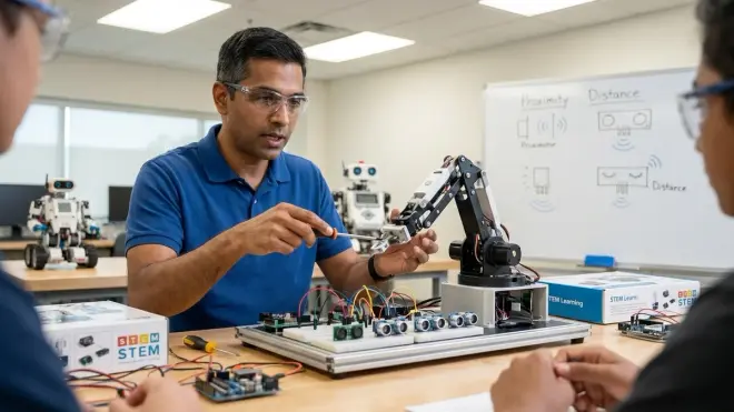
Ultrasonic rangefinders emit 40kHz sound pulses and measure time-of-flight to calculate distance, typically effective from 2cm to 400cm. The HC-SR04 module exemplifies this category—students trigger measurements with a 10μs logic pulse and read echo pulse duration. These sensors fail on sound-absorbing materials (foam, fabric) and return false readings when beam angle (typically 15°) catches multiple surfaces. They work identically underwater and in dusty environments where optical sensors fail.
Infrared proximity sensors measure reflected IR light intensity, functioning from 4cm to 30cm for sharp GP2Y0A21YK modules or up to 150cm for longer-range variants. Non-linear voltage-to-distance curves require lookup tables or polynomial fitting for accurate measurements. Surface reflectivity affects readings substantially—white paper returns stronger signals than black plastic at identical distances. Students learn these sensors excel at edge detection and line following but struggle with transparent or highly reflective surfaces.
Time-of-flight (ToF) laser rangefinders like the VL53L0X measure distances up to 2 meters with millimeter precision using modulated laser light and phase detection. These sensors ignore ambient light and surface color but cost 3-4× more than ultrasonic alternatives. The I²C interface and calibrated output make them ideal for students progressing beyond analog sensor challenges to learn digital communication protocols.
LiDAR (Light Detection and Ranging) modules like the RPLIDAR A1 provide 360° distance scanning, generating point clouds mapping surroundings. These units cost $100-150 and demand USB connectivity plus dedicated processing power for real-time data interpretation. They represent the jump from single-point sensing to environment mapping—the same technology in $30,000 autonomous vehicles, available to students willing to tackle higher computational complexity.
Environmental Sensors
Temperature sensors span analog devices like thermistors (changing resistance) and the TMP36 (linear voltage output) to digital I²C options like the DS18B20 (12-bit resolution, ±0.5°C accuracy). Students discover that response time matters—a thermistor in open air responds in seconds while one embedded in thermal epoxy takes minutes to stabilize. Submersible stainless-steel-encapsulated DS18B20 sensors enable water temperature monitoring for environmental monitoring kits tracking thermal pollution.
Humidity sensors using capacitive elements measure relative humidity 0-100% with ±2-5% accuracy. The DHT22 combines temperature and humidity in a calibrated digital module requiring only single-wire communication—though its 2-second minimum sampling interval frustrates students attempting rapid data logging before they read specifications.
Barometric pressure sensors like the BMP280 measure atmospheric pressure 300-1100 hPa, enabling altitude estimation within ±1 meter. Students working on weather stations or altitude-hold drones learn these sensors require temperature compensation and sea-level calibration to deliver meaningful data—practical exposure to why raw sensor values rarely equal physical quantities.
Gas sensors detect specific compounds: MQ-2 for propane and hydrogen, MQ-135 for CO₂ and ammonia, MQ-7 for carbon monoxide. These metal-oxide semiconductor devices require 24-48 hour burn-in periods and heater currents of 150-200mA—teaching students that some sensors demand patience and power budgeting. Air quality monitoring projects using these sensors have detected gas leaks, inadequate ventilation, and vehicle exhaust patterns, demonstrating citizen science applications.
The best environmental monitoring kits for citizen science projects typically integrate 4-6 sensor types with weatherproof enclosures and data logging capabilities, providing structured introduction to multi-sensor systems before students tackle custom integration.
Motion and Orientation Sensors
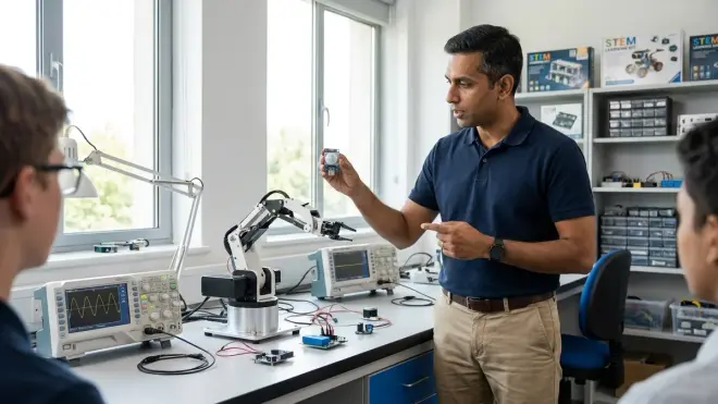
Accelerometers measure linear acceleration across X, Y, Z axes, detecting tilt, vibration, and impact. Three-axis MEMS accelerometers like the ADXL345 output digital values representing -16g to +16g ranges (where g = 9.8 m/s²). Students learn these sensors cannot distinguish gravitational acceleration from motion-induced acceleration—a stationary accelerometer reads +1g downward from gravity alone.
Gyroscopes measure angular rotation rate using Coriolis effect in vibrating MEMS structures. Three-axis gyroscopes report degrees-per-second around each axis but exhibit drift—accumulated errors when integrating rotation rates to calculate absolute orientation. A stationary gyroscope may report 0.1°/second bias, resulting in 6° error per minute of operation.
Magnetometers detect magnetic field strength and direction, functioning as electronic compasses. Three-axis magnetometers like the HMC5883L measure Earth's magnetic field to determine heading. Students encounter real-world sensor challenges: nearby motors, power supplies, and steel structures create magnetic interference requiring sensor calibration procedures mapping bias and scale errors.
Inertial Measurement Units (IMUs) combine accelerometers, gyroscopes, and often magnetometers with sensor fusion algorithms. The MPU-6050 integrates a three-axis accelerometer and gyroscope with an onboard Digital Motion Processor running calibration and filtering. Nine-axis IMUs adding magnetometers provide absolute orientation reference. These devices cost $3-15 and expose students to the same sensor fusion mathematics governing aircraft navigation systems.
Encoders count motor shaft rotations using optical or magnetic sensors detecting rotating disks with alternating patterns. Quadrature encoders with two sensors offset 90° determine rotation direction and speed. Students implementing PID motor control discover that 20 pulses-per-revolution hobby motor encoders lack resolution for smooth low-speed operation while 600 PPR industrial encoders enable precision positioning.
Vision and Imaging Sensors
Camera modules transform robotics from simple stimulus-response systems to pattern recognition platforms. The Raspberry Pi Camera Module v3 captures 12-megapixel stills and 1080p60 video, connecting via CSI interface to Raspberry Pi boards. OpenCV computer vision libraries enable students to implement color tracking, face detection, QR code reading, and AprilTag localization.
Students attempting vision-based projects encounter computational constraints: real-time image processing demands processing power beyond most microcontrollers. Raspberry Pi 4 handles basic OpenCV operations at 5-10 frames per second. Google Coral USB Accelerator adds hardware tensor processing enabling 30+ FPS object detection. This hardware progression mirrors industry transitions from CPU-only processing to GPU and specialized AI accelerators.
Line sensors simplify vision for specific applications. Arrays of 5-8 IR emitter-detector pairs detect line position under a robot with analog outputs indicating which sensors see dark versus light surfaces. The Pololu QTR-8RC reflectance sensor array costs around $10 and teaches analog signal processing and sensor fusion—students average readings from multiple sensors to calculate centerline position with greater precision than any single sensor provides.
Types and Variations of Robotics Actuators
Electric Motors and Motion Control
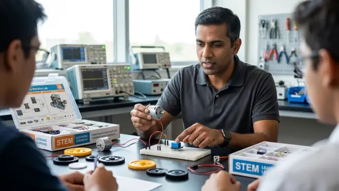
DC motors convert electrical power to continuous rotary motion through electromagnetic induction. Brushed DC motors use mechanical commutators switching current between coils as the rotor spins. They're available from 3V micro-gearmotors drawing 100mA no-load to 12V wheelchair motors consuming 10A under load. Students learn these motors lack inherent position control—applying voltage produces rotation but provides no feedback about speed or angle.
Gear motors couple DC motors to mechanical gear reduction, trading speed for torque. A 100 RPM gearmotor with 100:1 reduction ratio converts a 10,000 RPM base motor into 100 RPM output with 100× torque multiplication (minus friction losses). Students selecting drive motors for wheeled robots calculate required torque from wheel diameter, robot mass, and desired acceleration—the same mechanical engineering fundamentals underlying industrial conveyor design.
Servo motors integrate a DC motor, gearbox, position sensor, and control circuit into a single package. Hobby servos respond to PWM signals positioning the shaft ±90° from center (±60° for 180° servos). Standard servos provide 2-4 kg⋅cm torque; high-torque versions deliver 10-35 kg⋅cm. Students building robotic arms learn that servo torque ratings assume perpendicular force—actual lifting capacity depends on lever arm geometry and must account for servo weight.
Digital servos update position 300+ times per second versus 50 Hz for analog servos, providing faster response and better holding torque. They cost 50-100% more but eliminate the jitter plaguing analog servos in high-vibration applications.
Stepper motors rotate in precise angular steps controlled by pulsed coil energization sequences. Common stepper motors move 1.8° per full step (200 steps per revolution) or 0.9° per step (400 steps/revolution). Microstepping driver circuits subdivide steps into 2, 4, 8, or 16 microsteps, enabling smoother motion and finer position control. Students implementing 3D printers or CNC machines discover these motors maintain position without feedback sensors but lose steps if mechanically overloaded.
The servo motors vs stepper motors vs DC motors for robotics decision framework prioritizes specific application requirements: continuous rotation with speed control favors DC motors, precise angular positioning demands servos, and open-loop stepping with high holding torque suits steppers. No motor type handles all applications effectively.
Linear and Alternative Actuators
Solenoids produce linear motion by electromagnetic attraction pulling a ferromagnetic plunger into a coil. Push-pull solenoids can extend or retract based on polarity. Students building automated sorting systems or locking mechanisms discover that solenoid force decreases rapidly with distance—a solenoid rated for 2 kg force at 5mm travel may produce only 0.5 kg at 10mm.
Linear actuators extend DC motors or stepper motors through lead screws or rack-and-pinion gears converting rotary to linear motion. Industrial linear actuators with built-in encoders and limit switches cost $150-400 but provide position feedback and overload protection. Students building adjustable camera mounts or sample collectors learn these actuators enable precise millimeter-scale positioning across 100-500mm travel ranges.
Pneumatic actuators use compressed air driving pistons or inflating bladders. While common in industrial and competitive robotics (FIRST Robotics allows compressed air systems), pneumatic components require air compressors, pressure regulators, solenoid valves, and tubing—infrastructure rarely practical for home learning environments. Students interested in pneumatic systems typically encounter them first in organized robotics competitions with shared compressed air stations.
Shape-memory alloy (SMA) actuators use nickel-titanium wires that contract when heated by electrical current, producing linear motion. These actuators demonstrate materials science principles but suffer from slow response times (seconds per cycle), limited stroke length (3-5% of wire length), and efficiency below 5%. They suit applications where simplicity and light weight outweigh performance limitations—soft robotics grippers or biomimetic wing mechanisms.
Interface Devices
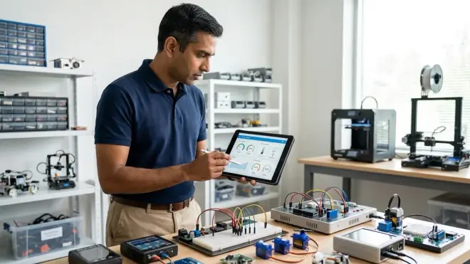
Relays function as electronically-controlled mechanical switches, allowing low-power logic circuits to control high-power AC or DC loads. Students building automated greenhouse systems use relays to switch 120VAC irrigation pumps, grow lights, and ventilation fans. Solid-state relays (SSRs) eliminate mechanical contacts and switching noise but cost 3-5× more than electromechanical relays.
LED displays and indicators provide human-readable output. Single LEDs signal system states. Seven-segment displays show numerical data. LED matrices and OLED screens render text and graphics. NeoPixel-style addressable RGB LED strips use single-wire serial protocols controlling hundreds of individually-programmable LEDs—students building wearable projects or room lighting learn the same control methods used in professional architectural lighting installations.
Speakers and audio actuators convert electrical signals into sound through electromagnetic or piezoelectric transduction. Piezo buzzers produce simple tones and alerts. Small 8Ω speakers coupled with audio amplifier modules enable speech synthesis or music playback. Students implementing voice feedback or alarm systems learn PWM audio generation, discovering that 8-bit 8 kHz audio consumes 64 kbit/s bandwidth and requires buffer management preventing audio dropout.
Essential Lab Specifications for Robotics Sensors and Actuators
Power Requirements and Supply Design
Educational robotics systems typically operate on 3.3V or 5V logic with 6-12V motor supplies. USB power (5V, 500-900mA) suffices for microcontroller, sensors, and LEDs but cannot drive motors. Rechargeable lithium-polymer batteries (7.4V or 11.1V 2200mAh packs) provide 45-60 minutes of mixed operation with motors.
Calculate total current consumption by summing all components at maximum simultaneous draw:
- Arduino Uno: 50mA
- Raspberry Pi 4: 600mA base + 500mA per USB device
- Servo motors: 200-2000mA each under load
- DC motors: 100-5000mA depending on size and load
- Sensor modules: 5-50mA each
- LED indicators: 20mA per LED
Add 25% safety margin and select power supplies or battery capacity accordingly. A mobile robot with four gear motors (1A each), six servos (500mA average), Raspberry Pi (1A), and sensors (200mA) requires 6.2A capacity—call it 8A with safety margin. This calculation determines whether USB power banks (typically 2.4A max per port) or dedicated battery packs are necessary.
Voltage regulators drop excess battery voltage to logic levels. Linear regulators (LM7805, AMS1117) waste voltage difference as heat—efficient only with small voltage drops. Buck converters (switching regulators) maintain 85-95% efficiency across wide voltage ranges but cost $2-5 versus $0.50 for linear regulators. Students learn thermal management when discovering a linear regulator dropping 9V to 5V while supplying 1A dissipates 4W as heat—enough to cause thermal shutdown without heatsinking.
Robotics actuator safety starts with power isolation: separate battery positive terminals for logic and motors sharing common ground prevents motor current from disrupting logic circuits. Fuses on motor supplies protect batteries from short-circuit damage. Emergency stop switches interrupt power to actuators while maintaining sensor and processor power for controlled shutdown.
Connectivity and Compatibility
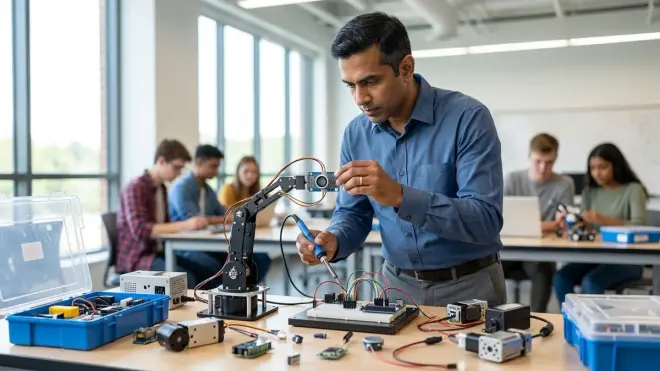
Arduino ecosystem (Uno, Nano, Mega) uses 5V logic, 16 MHz ATmega328P/2560 processors, and Arduino IDE C++ programming. Analog inputs accept 0-5V; 10-bit ADCs provide 4.9mV resolution. Digital pins source/sink 40mA maximum. Six hardware PWM channels control servos and motors. I²C (pins A4/A5) and SPI (pins 10-13) enable digital sensor communication. Students graduate from block-based Arduino Create to text-based Arduino IDE around age 11-12.
Raspberry Pi (Model 4B, 5) runs full Linux operating system, enabling Python, C++, Node.js, and other languages. 3.3V GPIO pins require level shifters for 5V sensors unless the sensors tolerate 3.3V communication. 40-pin header provides 26 GPIO pins, UART, I²C, SPI, and PWM channels. Camera and display connectors support official modules. USB ports connect keyboards, mice, and peripherals. Students learn Linux command-line navigation, package management, and remote SSH access—skills directly applicable to cloud servers and embedded Linux development.
ESP32 microcontrollers integrate WiFi and Bluetooth, dual-core 240 MHz processors, and 18 analog channels with 12-bit resolution. The 3.3V logic requires level shifters for 5V devices. Arduino IDE compatibility enables Arduino library use while exposing advanced features through ESP-IDF framework. Students building IoT sensor networks learn these boards cost $4-8 and provide connectivity that Arduino Uno lacks without additional shields.
Micro:bit targets ages 8-11 with simplified block programming and integrated sensors (accelerometer, compass, buttons, LED matrix). GPIO edge connector accepts alligator clips for beginners and standard headers for advanced users. The 3.3V operating voltage limits actuator types without external drivers. Students typically start here and transition to Arduino or Raspberry Pi within 6-12 months.
Most robotics sensor kits specify compatible platforms—verify before purchase that target controller is listed. Sensor datasheets specify operating voltage, communication protocol, and current consumption; actuator datasheets add stall current, torque curves, and speed ratings.
Expandability and System Growth
Plan progressive skill building through hardware expansion paths:
Phase 1 (Ages 8-10): All-in-one kits with pre-wired modules, magnetic mounting, and block programming. LEGO Mindstorms, VEX IQ, or similar platforms where sensors and actuators connect without breadboarding.
Phase 2 (Ages 11-13): Microcontroller development boards with breadboard prototyping. Sensor modules on breakout boards with labeled pins. Jumper wires and simple schematics. Arduino starter kits with 10-15 sensor types and motors demonstrate breadth before depth.
Phase 3 (Ages 14-16): Raw sensor components requiring support circuits. Datasheets specify operating conditions, interface requirements, and performance characteristics. Students design circuits in simulation software (Tinkercad, Fritzing) before building. Oscilloscopes verify signal quality. Multimeters measure voltage, current, and resistance during troubleshooting.
Phase 4 (Ages 17+): Custom PCB design consolidating breadboard prototypes. Surface-mount components reduce size and improve reliability. Professional CAD tools (KiCAD, Altium) generate manufacturing files. 3D-printed enclosures integrate mechanical and electrical design. Students produce portfolio-ready documentation including schematics, board layouts, assembly instructions, and test procedures.
Hardware platforms supporting this progression minimize equipment obsolescence. Sensors and actuators developed for Arduino work equally well with Raspberry Pi or ESP32 given appropriate level shifting. I²C and SPI protocols remain consistent across platforms. Programming concepts transfer between languages—a student mastering Arduino C++ transitions to Python with minimal adjustment.
Durability and Maintenance Considerations
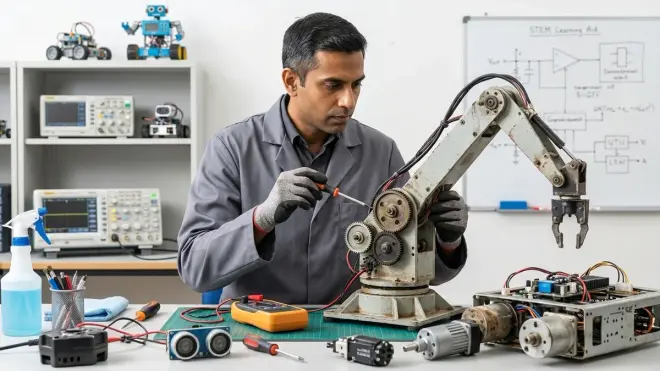
Student projects demand robust connections and physical resilience. Breadboard circuits tolerate dozens of assembly/disassembly cycles before developing intermittent connections. Dupont-style jumper wires maintain contact through 50-100 insertions; cheap wires fail sooner. Male header pins soldered to modules survive thousands of connections; friction-fit pins work loose.
Servos fail from water ingress, gear stripping, or potentiometer wear. Budget servos (sub-$5) last 50-100 operating hours; quality servos ($15-25) survive 500+ hours. Students learn maintenance practices: avoid stalling servos against mechanical limits (software limit implementation), don't exceed rated torque, keep electronics dry.
Motor brushes wear with use—budget DC motors show performance degradation after 100 hours; quality motors maintain specifications beyond 1000 hours. Gear reduction stages introduce backlash and friction losses; planetary gearboxes provide superior efficiency and longevity compared to spur gears but cost 50-100% more.
Sensor calibration drifts with temperature changes, mechanical stress, and aging. Sensor calibration in student robotics establishes testing protocols: verify ultrasonic sensors against tape-measure distances, compare temperature sensors to calibrated thermometers, cross-check IMU readings against known orientations. Students documenting pre/post-project calibration data demonstrate measurement discipline valued in research and quality-control roles.
Frequently Asked Questions
What sensors do I need to build a basic line-following robot? A line-following robot requires infrared reflectance sensors detecting dark lines on light surfaces or vice versa. A five-sensor array positioned across the robot's front edge provides line position data. Two DC gear motors with an H-bridge driver enable differential steering. An Arduino Uno or equivalent microcontroller reads sensor values and controls motors. This configuration costs $25-40 in components and teaches analog sensor reading, threshold comparison, and proportional steering control.
Can I use 5V sensors with Raspberry Pi's 3.3V GPIO pins? Raspberry Pi GPIO pins tolerate 3.3V maximum input voltage; 5V signals risk permanent damage. Many 5V sensors output 5V logic levels that require level shifters converting signals to 3.3V before reaching GPIO pins. Bidirectional level shifters using MOSFETs cost $1-2 and protect both the sensor and Raspberry Pi. Some modern sensors operate on 3.3V-5V supply voltage and automatically match their output to supply voltage, eliminating level-shifting requirements—check sensor datasheets for "logic level" specifications.
How do I calculate the power supply needed for multiple servo motors? Sum the stall current of all servos that might operate simultaneously, then add 25% safety margin. A typical hobby servo draws 100-200mA idle and 500-1000mA stalled; high-torque servos draw 1500-2500mA stalled. Six standard servos might require 3.6A maximum (6 × 600mA average). A 5V 5A switching power supply provides adequate capacity. Never power servos directly from Arduino's voltage regulator—the 500-800mA limit causes brownout resets. Use external 5-6V supplies with common ground to the Arduino.
What's the difference between analog and digital sensors in practical use? Analog sensors output voltage levels proportional to measured quantity; microcontrollers read these through ADC pins and must convert values to physical units using calibration formulas. Digital sensors contain internal microcontrollers performing measurement, calibration, and unit conversion, then transmit results via I²C, SPI, or serial protocols. Digital sensors cost 50-200% more but provide calibrated data in standard units, often with higher precision. Analog sensors teach signal conditioning and ADC concepts; digital sensors teach communication protocols and device drivers.
At what age should students transition from pre-wired sensor modules to breadboard circuits? Students demonstrate readiness for breadboard prototyping when they can follow simple wiring diagrams, identify positive/negative/signal connections, and use multimeters to verify connections. This typically occurs ages 11-13 but varies with prior experience and fine motor skill development. Start with large-format breadboards, pre-stripped jumper wire kits, and circuits requiring 5-8 connections. Students struggling with breadboard reliability benefit from spending another 6-12 months with pre-wired modules before revisiting—rushing this transition produces frustration and equipment damage without learning benefit.
Building Toward Industry-Standard Competencies
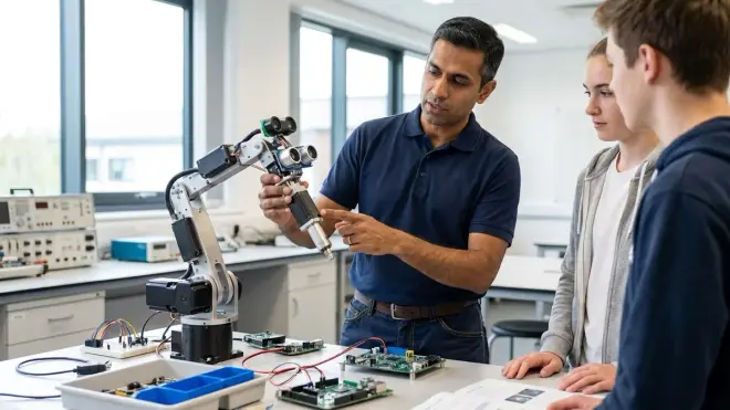
The robotics sensors and actuators forming educational projects use the same fundamental principles as industrial automation systems costing thousands times more. Students wiring an ultrasonic sensor to measure bin fill levels learn the identical time-of-flight calculation used in $20,000 warehouse inventory systems. Those implementing PID motor control for line-following robots deploy the same algorithm managing CNC machines, industrial mixers, and climate control systems.
This direct transferability creates leverage: hours invested in student projects build skills with decades of career applicability. The 2026 manufacturing sector added 47,000 automation technician roles requiring sensor integration, PLC programming, and actuator troubleshooting. The engineering services sector posted 12,000 positions demanding embedded systems development, motor control, and signal processing. These jobs pay $55,000-85,000 starting salaries—reflecting market demand for hardware-software integration skills that most computer science curricula ignore.
Students progressing through the hardware layer described here develop technical judgment distinguishing them from pure software developers: which sensor types suit specific applications, how much actuator torque a mechanical system requires, where signal conditioning becomes necessary, what failure modes various components exhibit. These decisions shape whether projects work reliably or fail intermittently—the difference between portfolio pieces demonstrating competence and abandoned prototypes collecting dust.
I ran both my children through this exact progression: magnetic sensor modules at age 9, breadboard circuits at 12